CVAC Solution
The CVAC technology is composed by two camshafts, one for intake and other for exhaust valves similar to a Dual Overhead Camshaft (DOHC). The cams are designed to have the desired lobe shapes for each optimum valve opening/closing settings in a 3D surface.
CVAC cams can be freely designed to have different lobes with different lobes centre, duration and lift. The lobes shall only have smooth shapes that will allow the follower to be moved by the cam. This eliminates the need of egg-shaped cams.
The figure below is a simple CVAC cam example for a gasoline intake cam. The opening goes from L1 to L4, having various different lobes in between them, for example, L2 and L3. The lobes quantities depend on the CVAC cam dimension and follower positioner precision.

The figure above represents a classical timing diagram, with different lobes. But this diagram lacks of a third axis, the follower position, that defines which lobe is selected and thus how the valve will open.
The figure below is a 3D timing diagram for the same CVAC cam with the third axis showing the follower position. It shows that there are various different lobes to be selected between L1 and L4. In particular, it also shows L2 and L3 as in the 2D diagram.
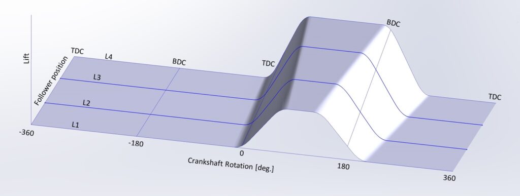
The example above has a constant variance between L1 to L4, but it’s only to show a simple example.
The only limitation is that the variance shall be continuous with no sharp edges to allow the positioner to move the follower from one lobe to another. In the image below, you can observe another gasoline intake CVAC cam design with non-constant lobes variance.
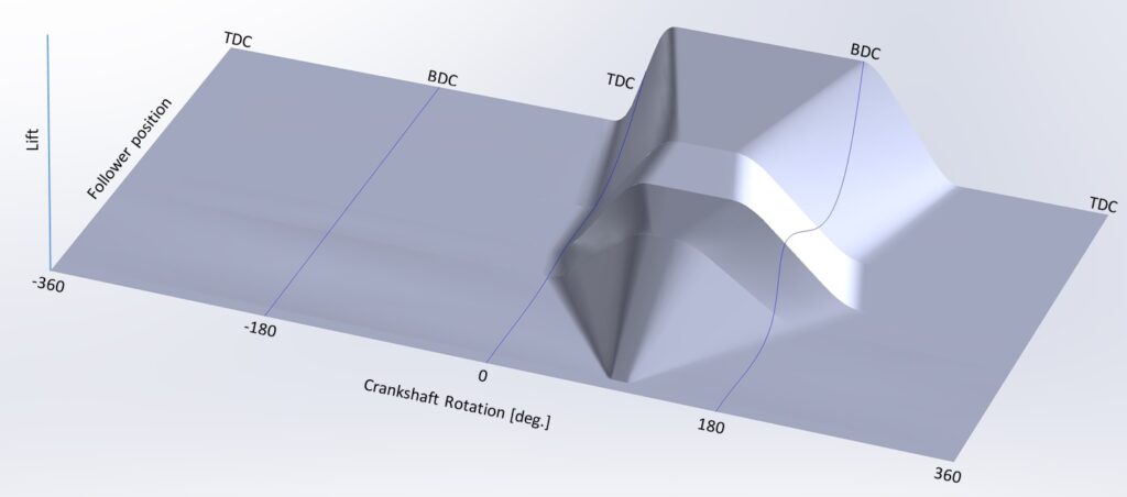
CVAC Intake and exhaust cams should have its own design optimized for each function. Each camshaft can set the lobe position independently from each other. Also each cylinder CVAC cam follower position can be set independently. This is particularly interesting for cylinders deactivation.
CVAC has mostly the same variation capability as the state of the art Electro pneumatic Camless solution. Thus, CVAC and Camless camshafts have similar capabilities and it is expected that CVAC will reach around 15% fuel consumption reduction and more than 40% on power and torque gains, as Camless systems.
As CVAC is a mechanical solution there is no limitation on valve mass. Also by being Desmodronic there is no RPMs limitation. The cam rotation is done as a standard camshaft using a belt or chain reducing the catastrophic failure possibilities as in camless solutions. Furthermore, it’s simpler to produce and maintain.
CVAC has unparallel capabilities compared to any other mechanical VVT and will help to design Euro 7 engines, with minimal emissions but retaining performance capabilities.
CVAC Advantages

First Fully variable and Fully mechanical solution

Compatible with any type of reciprocating internal combustion engine

Desmodronic

Can combine different cycles (Otto, Atkinson, Miller and others)

Cylinder and valves independent variability

Cylinder deactivation by compressing or blowing air

15% fuel consumption reduction (expected)

40+% on power and torque gains (expected)
CVAC fully mechanical solution

As all mechanical camshafts, CVAC uses cams and followers. The timing variability is achieved by selecting different cam lobes using an electromagnetic positioner. The lobes shapes are limited to a continuous path on where the follower is able to mechanically follow the cam surface. Considering this limitation, the lobes can be designed with the desired slope, lift, phase and duration. The lobes do not need to follow the standard egg-shaped cams.
As the functionality of the camshaft is to open and close valves, typically the most effective way is a trapezoidal shape with rounded edges to allow the follower to be easily moved by the cam. CVAC doesn’t have this limitation and other shapes could be used. This greatly broadens the cams design possibilities and expands their options to optimize the engine output.
CVAC 3D Cam
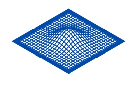
The solution uses an axial cam that is 3D shaped to have a variety of different lobes to be used at different RPMs and loads, as per engine designer needs. Each of these lobes can be selected by an electromagnetic positioner controlled by the engine’s ECU.
CVAC gives the engine manufacturer freedom to design the optimum valves timings at all engine rates. As a fully mechanical solution, the only design limitation is that the cam shape has to have smooth variations or edges to easily move the follower.
Lobe Flexibility
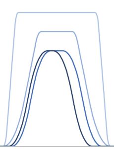
CVAC cam lobes are designed as a continuous variable 3D shape with minimum design constrains. As all mechanical cam and follower camshaft, each lobe shall be a continuous surface with rounded edges.
In the CVAC cam example it can be observed (from the darker to brighter cam diagram): (1) a standard camshaft lobe, (2) the same shape with added duration and shifted some degrees, (3) lobe with extra lift, duration and sharpened top edges and (4) a performance lobe with full lift, maximum opening velocity (lifting slope) and aggressive valve landing.
This design can apply to the intake cam and a completely different design can be used for the exhaust cam.
Combines different cycles
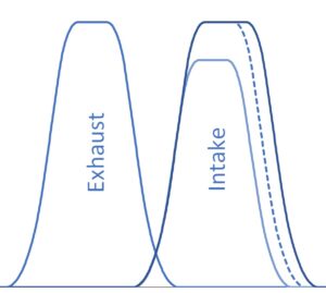
The CVAC can combine Otto cycle with other ones. The Otto cycle has similar lobe shapes for exhaust and intake valves. To achieve a consumption reduction, Atkinson or Miller cycles can be used by modifying the intake lobe (dashed line). On an Atkinson cycle (darker line) the intake valve is left open at some more degrees (a little more time), increasing the duration and center of the lobe. For Miller cycle (brighter line), the intake lobe with less duration and lift with a shifted center.
Cylinder deactivation
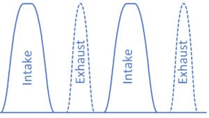
CVAC can deactivate cylinders to reduce the consumption at lower RPMs and loads. This can be done in the classic way, closing the intake and exhaust valves in all four strokes. But CVAC can also deactivate them by alternately opening the intake and exhaust valves. The advantage of this extra CVAC deactivation capability is that the deactivated cylinder can be used as a blower and not lose energy to compress air that will not be used to produce energy.
Desmodronic
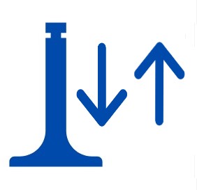
The CVAC works in a Desmodronic style (the cam pushes the valves down and pulls them up), and thus it doesn’t require a return spring. This feature allows high revving cams without valves floating issue (when the closing springs cannot follow the cam). Nowadays, this issue is solved with high force or pneumatic springs, but a Desmodronic cam requires less energy as it doesn’t have to compress the return springs, reducing the engine losses. Also, it allows a smooth landing of the valve on its seat even using big rates of lifts or angle, eliminating the valve seat worn or damage.
Simple and Compact design

CVAC cam design is similar to a traditional Double Over Head Cam (DOHC). Uses traditional timing belts or chains. Aside of the CVAC camshaft, the only additional component to be added to a traditional non variable camshaft is a positioner per cylinder and cam.
The CVAC has a simple design compared with different Variable Valve Actuator available on the market. The only complex component are the 3D cams, but they can be shaped with a standard CNC machine.
Current CVAC camshaft requires a valve head with a similar shape and dimension to the standard ones. The Desmodronic solution allow shortened valves with up to 50% of standard lengths. This allows further CVAC deigns to reduce the valves head height.