CVAC Diesel
The Variable Valve Actuation (VVA) on Diesel engines is not as widely used as in Gasoline ones. But it has a wider range of possibilities that can be used to optimize Diesel engines, in particular for medium and heavy duty ones.
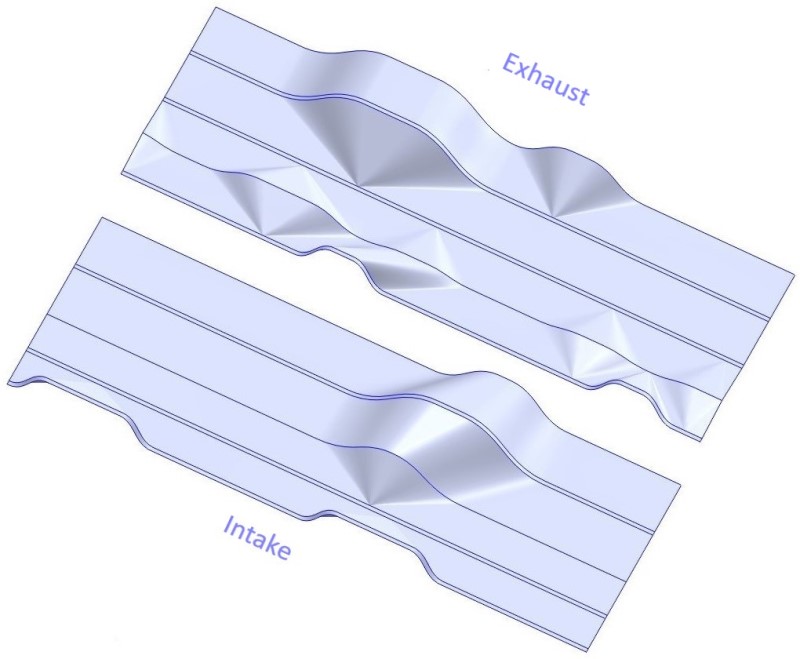
CVAC free lobes design allows grater optimizations than current market solutions. The following CVAC diesel cam design example shows 9 working modes, 4 more than the best VVA on the market. This cam design example is meant to show CVAC capabilities, not the optimum cam for an engine.
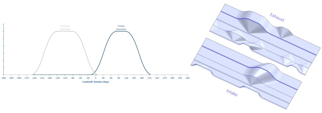
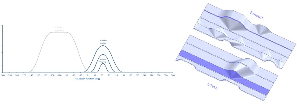
The 2D diagram shows different Miller cycles lobes paths (with different lifts and duration) that can be selected to have the optimum intake valve opening lobe to reduce consumption and emissions.
The horizontal lines in the 3D diagram show the cams working areas. A mode is defined as a set of intake and exhaust working area.
2 - Intake Miller mode
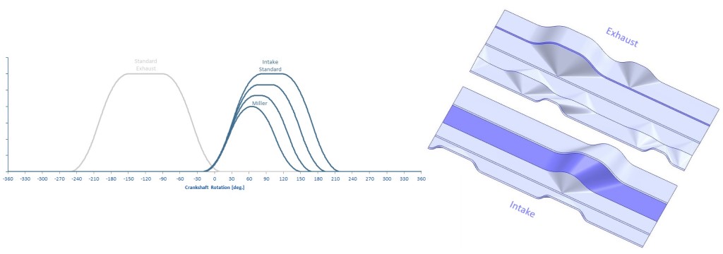
On low loads and RPMs the use of Miller cycle, instead of the classical diesel one, will allow a reduction on consumption and emissions. In this example, CVAC uses the early intake valve closings method to control the effective compression ratio for Miller cycle. The valve closing point can be varied to optimize the Miller cycle on various RPMs and engine loads.
The 2D diagram shows different Miller cycles lobes paths (with different lifts and duration) that can be selected to have the optimum intake valve opening lobe to reduce consumption and emissions.
The 3D diagram shows the Intake miller working area. The follower will be placed in the optimum horizontal path inside this area.
3 - Intake LIVO mode
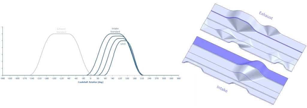
The Late Intake Valve Opening (LIVO) is designed to optimize the engine for minimal load conditions and idling. In this mode the intake valves movement is reduced to speed up the inlet charge into the cylinders.
The CVAC cam diagrams below show the late intake opening possibilities, from the idle position to up to standard valve opening.
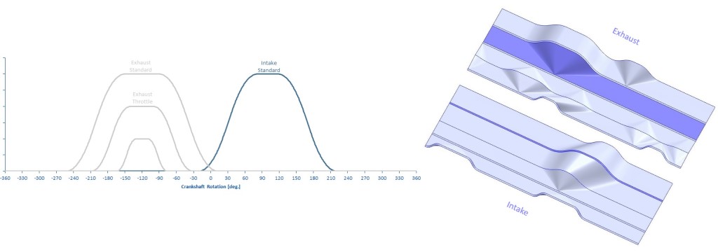
4 - Intake Internal Throttle mode
An Intake throttle is added to some diesel engines to regulate the intake manifold pressure to help increase EGR rates. Also these valves allow low minimum flow for smooth engine to shut down. The same effects can be achieved by CVAC as showed in the below diagrams.
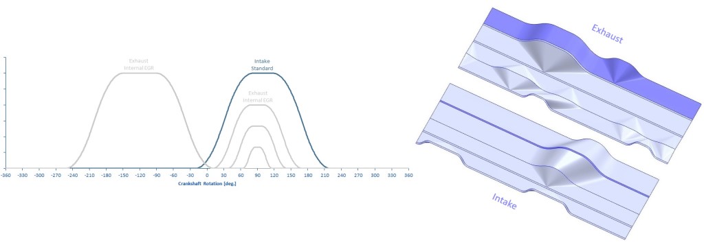
5 - Internal EGR mode
An exhaust gas recirculation (EGR) valve is used on most of modern engines. The EGR system is used to reduce the NOx produced by the engine while the after treatment system converts most of the engine-out emissions into safer gases before releasing them into the atmosphere, but it is required to be used at a minimum temperature before it is effective.
There are various techniques to produce the internal EGR process. For this CVAC cam design example, the Exhaust valve bump method is used. This method opens the exhaust valve during the intake stroke, allowing residual exhaust gases into the cylinder, increasing the mixture temperature
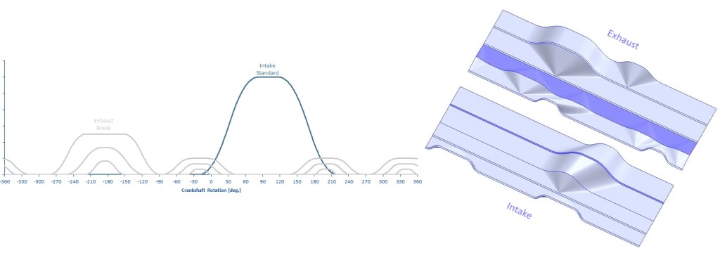
6 - Engine Breaking mode
Engine braking is a basic capability of an internal combustion engine. This feature is key for trucks to reduce speed without wearing the service breaks. A common solution is to add a valve to the exhaust that is closed (when the trucks needs to slowly reduce its speed) to increase engine braking force.
A more efficient solution is using Variable Valve Actuation (VVA) to increase the engine braking power, instead of the exhaust valve. Current VVA pneumatic solutions restrict exhaust valves lobes by lowering lift and duration.
CVAC example below is similar to market solutions that show that it can handle complex opening diagrams. An extra benefit, that it’s not possible with current solution, is that different openings heights and times can be selected applying the precise breaking force needed by the driver.
CVAC solution gets rid of egg-shaped cam lobes (of the current pneumatic solutions) and allows different lobes designs for any engine RPMs, allowing maximum braking power at any engine speed.
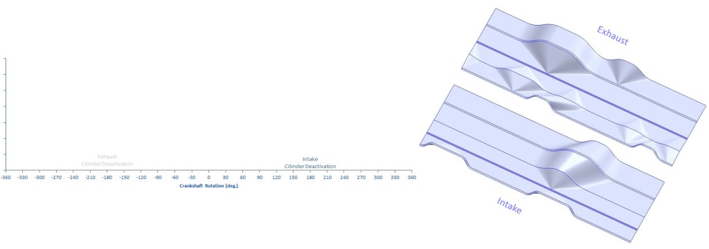
8 - Cylinder deactivation mode
CVAC can deactivate cylinders to reduce the consumption at lower RPMs and loads. This can be done in the classic way, closing the intake and exhaust valves in all four strokes. CVAC can control every cylinder separately, so any amount of cylinders can be deactivated at any given time.
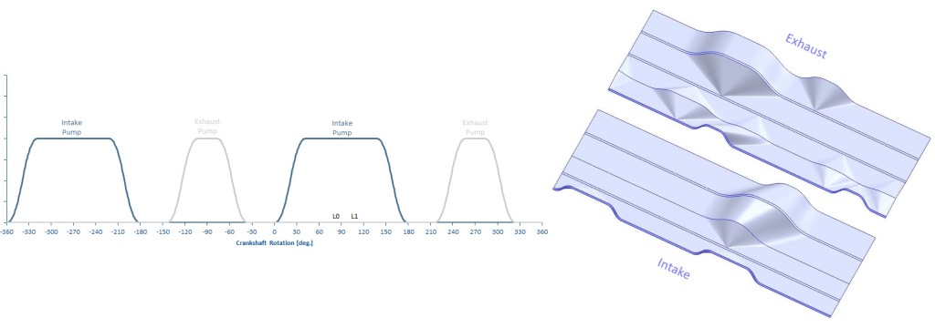
9 - Air pumping mode
One or more cylinders can be used as a pump by alternately opening the intake and exhaust valves. This could be used as a cylinder deactivation technique, using some of the engine power (active cylinders) to power cylinders in pumping mode to compress air and store it for the air braking system. An extra valve in the exhaust manifold shall be added (for each cylinder) that would rout this compressed air to the tank. This would make the air compressor redundant.
Also, the compressed air could be routed (by the same exhaust manifold valve) to the intake manifold using it as a classical intake compressor.
A third usage could be to have a separated air tank reservoir, that could be used to inject air into the manifold when extra power at low RPM is needed (and the turbo does not generate much compression). This extra air would give extra torque at low RPMs and could replace a standard electrical hybridization at lower manufacturing cost and system weight.
Conclusion
The CVAC design capabilities have been shown in these particular Intake and Exhaust CVAC cams example, that double the modes available on the VVA market. Diesel Engine manufacturers would be able to design CVAC optimum cams for their applications with more functionalities.
Euro 7 standards will be difficult to achieve, especially by heavy duty diesel engines. CVAC is the right new technology that will help diesel engine manufacturers to comply with Euro 7.
